Maintaining a crystal-clear swimming pool requires more than just a sunny disposition and a love for leisurely dips. At the heart of every sparkling oasis is a crucial yet often underestimated component – the pool pump. However, the days of choosing a pump based solely on horsepower ratings are behind us. Today, the process of correctly sizing a pool pump demands careful evaluation and a nuanced understanding of your pool’s unique needs.
In this guide, we’ll delve into the art of selecting the right pool pump for your swimming pool. Gone are the days when bigger meant better; modern pumps are designed for efficiency, and selecting the wrong size can lead to inefficiencies and unnecessary expenses. We are going to simplify the complexities of pool pump sizing, ensuring that you make an informed choice that not only keeps your pool water pristine but also minimizes energy consumption.
To aid you in this endeavor, we’ve included a comprehensive overview of different pump types, accompanied by a convenient comparison chart at the bottom of this page. Our pump ratings will help you sift through the options with confidence. Once you’ve narrowed down your selection, simply click on the brand of your choice for in-depth product information. Prepare to understand the world of pool pump sizing and discover how to transform your pool into the ultimate aquatic paradise while keeping your costs in check.
To determine the right size for your pool pump, you must consider two essential factors:
Flow Rate (GPM – Gallons Per Minute): This represents the volume of water your pump needs to circulate in a minute. It’s like measuring how fast the water flows through your pool system.
Total Dynamic Head (TDH): TDH accounts for the resistance that your pool system encounters as water travels through pipes, filters, and other equipment. It’s like calculating the effort needed to push water through all the components.
These two factors, flow rate and total dynamic head, work together to ensure your pool pump is neither too powerful nor too weak for the job. By understanding these concepts and using them as a guide, you can confidently choose the correct pool pump size for your specific pool setup.
In this article, we will provide clear and practical examples to guide you through the process of calculating and obtaining both the flow rate (Gallons Per Minute, GPM) and the Total Dynamic Head (TDH) for your pool system.
In many cases, builders tend to use 2 horsepower pumps in pool installations simply because it’s the common practice, and they don’t want to risk losing a sale by using a smaller pump. However, selecting the right pump size is crucial to prevent unnecessary electricity consumption and reduce wear on your pool equipment. In this guide, we’ll walk you through the steps to properly size a pool pump, helping you make a more informed and efficient choice for your pool system.
For easy understanding we are going to be using an example of 20000 gallons pool of water as explained in details below.
We have a swimming pool of 20000 gallons of water, and need a turnover of 8 hours The pipe length from the swimming pool to the pump and from the pump to the pool is 30 meters, the pipe diameter is 2 inches, the piping system has 6 in number 90° Standard Elbows, 3 in number 45° Standard Elbows, 4 fully open Ball Valves. Vertical distance from the lowest pool bottom to the centre of the pump is 2 meters and vertical distance from the pump’s centre to the highest discharge point into the pool is 0.5 meters.
Determine the pool pump need for this pool?
Table of Contents
Determine the minimum Flow Rate (GPM – Gallons Per Minute).
Flow rate in gallons per minute (GPM) in a swimming pool refers to the speed at which water is circulated through the pool’s filtration and circulation system.
It measures how many gallons of water pass through the system in one minute. This parameter is essential for maintaining water cleanliness, evenly distributing pool chemicals, and preventing issues like stagnant water or algae growth.
A proper flow rate ensures that all the pool water is filtered and treated within a specific time frame, typically 8 to 10 hours called turn over, to keep the pool water in good condition for swimming pool
“Turnover” in the context of a swimming pool refers to the rate at which the entire volume of pool water is circulated, filtered, and treated by the pool’s circulation system. It is typically measured in hours and represents how long it takes for the pool pump to move an amount of water equal to the total pool volume through the filtration and treatment processes.
Determine the Number of Gallons to be Pumped per Hour
To calculate the number of gallons that should be pumped per hour to clean the entire pool water, you should decide the turnover time. Basing on the standards, the turn over should be between 8-10 hours. In the calculation we are going to use 8 hours as turnover as given in the example above.
To do this, divide the total number of gallons of water in your pool by 8.
For a 20000-gallon pool, the calculation is as follows:
20,000 gallons ÷ 8 hours = 2,500 gallons per hour
So, you would need to pump 2,500 gallons per hour to clean all the water in your 20,000-gallon pool in eight hours
Convert Gallons per Hour to Gallons per Minute (GPM)
Since pumps are usually rated in gallons per minute (GPM), divide the gallons per hour obtained above by 60. The 60 represents the number of minutes in an hour.
We obtained 2,500 gallons per hour, so:
2,500 ÷ 60 = 41.67 GPM (gallons per minute), which is the flow rate you need for your pump.
So we round off this to 42 Gallons Per Minute (GPM)
So, the minimum flow rate for a 20,000 gallon pool is 42 gallons per minute for a turn over of 8 hours.
Table showing minimum flowrate in gallons per minute (GPM) for common pool sizes for turnover of 8 and 10 hours
If you pool volume is not included in the table above, use the formula above to calculate the minimum Gallons per minute required for your pool.
Determine the maximum flow rate of the system.
The maximum flow rate in a pool system is limited by the size of the piping and the capacity of the equipment used. These factors collectively dictate the highest rate at which water can circulate and move through the pool system.
Efficient flow rates in a pipe refer to the ability to move water through it while minimizing energy loss. The efficiency of water flow in a pipe is affected by the speed at which the water moves. At lower speeds, there is less turbulence and friction, allowing for smoother water flow. However, once the water velocity surpasses approximately six feet per second (6 fps), there is a noticeable decrease in system efficiency.
This loss in efficiency is primarily due to several factors, including the development of swirling patterns and turbulence in the water as it moves faster. These disturbances counteract the smooth and efficient flow of water through the pipe. Friction also plays a significant role in reducing efficiency and is typically measured as friction losses within a plumbing system. As the velocity of water increases, so do the friction and overall losses within the system.
To ensure the best flow efficiency, it’s important to consider the pipe size. Different pipe materials and sizes have specific maximum flow efficiency values at 6 fps. These values help in determining the optimal pipe size for a given application to minimize energy consumption and maintain a smooth water flow.
The first step in assessing flow rate is to examine the pool system’s plumbing.
Take, for example, a 1.5-inch PVC pipe, can handle a maximum flow rate of 44 gallons per minute. In this context, having a pump with a capacity of 120 gallons per minute would be ineffective since the pipe can only accommodate 44 gallons per minute. Using an oversized pump in such cases can put excessive stress on the plumbing and potentially lead to serious damage on the system.
The table below lists the maximum flow in GPM based on plumbing size and water velocity. APSP-7 Requires: 6 FPS Suction side, 8 FPS Return/discharge side maximum for residential pools.
T2
Pool size (inch)
MAXIMUM FLOW IN GPM at 6FPS and 8FPs
6 FPS
8 FPS
1.5”
38 GPM
51 GPM
2”
63 GPM
84 GPM
2.5”
90 GPM
119 GPM
3”
138 GPM
184 GPM
4”
238 GPM
6”
540 GPM
In swimming pool pipes design We should use water velocity of 6FPS because it is the maximum velocity for suction side and smaller than the velocity for discharge side. It is a reasonable spot below the maximum allowable velocity and a common target for plumbing.
water velocity of 6FPS is the best velocity for swimming pools
Best efficient PVC pipe sizes for various sizes of swimming pools at water velocity of 6FPS for a turnover of 8 hours and 10 hours
T3
Pipe size (inch)
8 hours turn over
10 hours turn over
Pool size (gallons)
Pool size (gallons)
1.5”
below 18,240
below 22,800
2”
18,240 to 30,240
22,800 to 37,800
2.5”
30,240 to 43,200
37,800 to 54,000
3”
43,200 to 66,240
54,000 to 82,800
4”
66,240 to 114,240
82,800 to 142,800
6”
114,240 to 260,160
142,800 to 324,000
Let’s obtain a pipe size for our example
The pool size in the example is 20,000 gallons, from the table below for a turnover of 8 hours, 20,000 gallons is between 18,240 and 30,240 gallons which is a 2” pipe
The best PVC pipe size for 20,000 gallons pool is 2” pipe for a turnover of 8 hours.
The values in the table below are calculated from the table above for maximum flow rate through each pipe.
In our example we are using 2” pipe, from the table T2 above the maximum flowrate through 2” pipe is 63 GPM
Desired flow rate
The desired flow rate must be between the minimum flow rate and the maximum flow rate.
The average of the minimum and maximum rates is the Desired Flow Rate
check FILTER FLOW RATE in your pool. Every filter has a specific maximum flow rate it can handle. Going beyond this limit can lead to improper filtration and potential damage to the filter. Staying within the recommended flow rate ensures efficient operation and prolongs the filter’s lifespan.
Recommended flow rates for different sizes of SAND FILTERS
Recommended flow rates for different sizes of SAND FILTERS
Tank Diameter
19 “
21 “
24 “
30 “
36 “
Surface Area
1.8 Sq. ft.
2.3 Sq. ft.
3.1 Sq. ft.
4.9 Sq. ft.
6.9 Sq. ft.
Max Flow Rate
40 GPM
50 GPM
60 GPM
100 GPM
140 GPM
Recommended flow rates for different sizes of CARTRIDGE FILTERS
Recommended flow rates for different sizes of CARTRIDGE FILTERS
Surface Area
100 Sq. ft.
200 Sq. ft.
300 Sq. ft.
400 Sq. ft.
500 Sq. ft.
Max Flow Rate
38 GPM
75 GPM
112 GPM
150 GPM
150 GPM
Best Flow Rate
30 GPM
50 GPM
75 GPM
100 GPM
125 GPM
Recommended flow rates for different sizes of D.E FILTERS
Recommended flow rates for different sizes of CARTRIDGE FILTERS
Surface Area
100 Sq. ft.
200 Sq. ft.
300 Sq. ft.
400 Sq. ft.
500 Sq. ft.
Max Flow Rate
38 GPM
75 GPM
112 GPM
150 GPM
150 GPM
Best Flow Rate
30 GPM
50 GPM
75 GPM
100 GPM
125 GPM
Choosing pool filter
The filter chosen should have a maximum flow rate which is higher than that of the pipe size chosen (plumbing system)
In our example
Maximum flow rate for the 2” pipe is 63 GPM
We are going to use sand filter.
So from the table of sand filters, we are going to use 30 “, 4.9 Sq. ft. and maximum flow rate of 100 GPM
The Filter chosen has a higher maximum flow rate compared to that of the plumbing system.
If we are to use a DE filter, we choose one tha does not exceed 63 GPM which is the maximum flow rate for the plumbing system and close to the desired flow rate. In this case it would be 36 Sq. ft., 72 GPM and 54 GPM DE filter.
Total dynamic head
Here we are going to explain and calculate the total dynamic head of the pool system.
Total Dynamic Head (TDH) is the sum of various factors that determine the energy required by a pump to move fluid through a system. It represents the total resistance the pump needs to overcome to maintain the desired flow rate. Here are the factors considered when calculating Total Dynamic Head:
Static head (HS) refers to the vertical distance between a reference point and the water level in a fluid system, typically a liquid like water. It represents the potential energy that the fluid possesses due to its height above a specific point.
Losses due to friction in pipe length (Hf), often referred to as major losses, occur when a fluid flows through a pipe. These losses result from the friction between the moving fluid and the interior surface of the pipe. This can be done using the Darcy-Weisbach equation or empirical methods.
Losses in fittings (H fittings), also known as minor losses refer to the reduction in pressure or energy that occurs when a fluid flows through various components in a piping system, such as bends, valves, elbows, and other fittings.
The formula for calculating Total Dynamic Head (TDH) is:
For easy understanding we are going to be using an example in all the formulars , we going to use our example in all the calculations.
The pipe length from the swimming pool to the pump is 26 meters, the piping system has 6 in number 90° Standard Elbows, 3 in number 45° Standard Elbows, 4 fully open Ball Valves. Vertical distance from the lowest pool bottom to the centre of the pump is 2 meters and vertical distance from the pump’s centre to the highest discharge point into the pool is 0.5 meters.
The swimming pool is of 20000 gallons of water, we obtained the desired flow rate as 53 GPM for a turnover time of 8 hours. It depends upon your choice.
Size the correct pool pump needed?
To size the pump correctly we need the Total dynamic head in feet and flow rate in Gallons per minute
We have already obtained the GPM as 53 gallons per minute for a turnover of 8hours, no we need TDH In feet.
TDH = HS + Hf + H fittings
Lets start with static head.
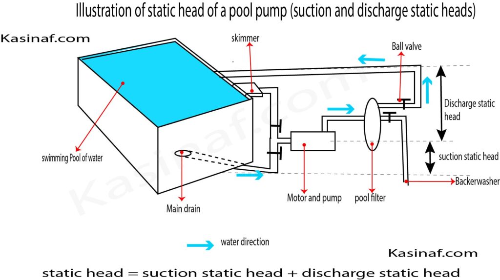
Static head
Refers the cumulative vertical distance that water needs to overcome as it navigates through a fluid system. It is divided into two, suction static head and discharge static head.
Suction Static Head: This refers to the vertical distance between the water level in the pool and the pump’s inlet. It represents the height that the pump needs to lift water from the pool. A greater suction static head requires the pump to work harder to overcome the gravitational force and draw water into the system. Factors such as pool elevation and the height of the water column contribute to the suction static head.
Discharge Static Head: This is the vertical distance between the pump’s outlet and the highest point where the water needs to be delivered. It represents the height that the pump needs to push water against gravity to reach its intended destination, such as the pool’s return jets or other equipment. Similar to the suction static head, the discharge static head contributes to the overall resistance that the pump must overcome to move water effectively.
Density of water (ρ) is 1000 kilograms (kg/m³) The dynamic viscosity of water at room temperature (around 20°C or 68°F) is approximately 0.001 kg/(m·s)
μ = 0.001 kg/(m·s)
lets substitute in the formular for Re
Re = (1000*1.645*0.0508)/ 0.001 = 66395.6
Re = 83566
So from the table above Re > 4000, the flow regime is turbulent, therefore use Empirical correlation to obtain the Darcy Friction factor (f)
Express the Reynolds number Re obtained in scientific form
Re = 83,566
Re = 8.3×10⁴
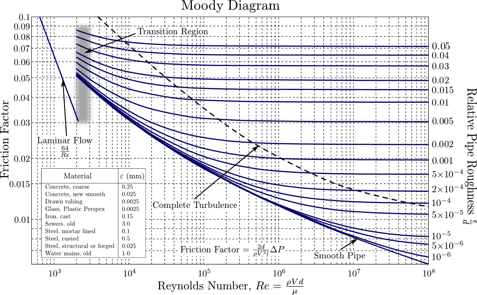
Now use the moody diagram to obtain the friction factor (f)
To use the moody diagram, you have to be with the Reynolds number (Re) , we have calculated it above, and the type of material of the pipes used for example plastic, steel etc.
Relative pipe roughness varies depending on the material used as shown in the key of the moody diagram. Use the key on the moody diagram to determine the relative roughness of your pipe.
In the example of this article we used plastic pipe (PVC)
In the example Re is 8.3×10⁴ and the relative roughness for plastic (PVC) is 0.0025
Locate Your Reynolds Number and Relative Roughness on the Moody Diagram:
The Moody diagram is a graph that relates the friction factor (f) to the Reynolds number (Re) and the relative roughness (ε/D). It’s a log-log plot with the x-axis representing Reynolds number (log scale) and the y-axis representing the friction factor (f). Various curves on the Moody diagram correspond to different values of relative roughness.
Scale for X axis (for Reynolds number), each small division represents 1.11
The head loss due to friction is 1.906 meters of water.
Head loss due to fittings (Hfitting) or Minor losses
Refers to the reduction in pressure or energy that occurs when a fluid flows through various components in a piping system, such as bends, valves, elbows, and other fittings.
Hfitting = (N*K*V2)/2g
Where
Hfitting is the minor head loss due to fittings ie valve, bends, tees etc
N is the number of fittings
V is the velocity of water
g is acceleration due to gravity
K is the friction factor. The fiction factor is different for various types of fittings
Resistance Coefficient K of commonly used fittings
Friction Losses in Pipe Fittings
Resistance Coefficient K (use in formula hf = Kv2/2g)
Nominal pipe size
Fitting
LD
1.5“
2”
2.5 – 3”
K Value
Ball Valve
3
0.06
0.06
0.05
Standard 90° Elbow
30
0.63
0.57
0.54
Standard 45° Elbow
16
0.34
0.3
0.29
Standard Tee Thru-Flow
20
0.42
0.38
0.36
Standard Tee Thru-Branch
60
1.26
1.134
1.08
Globe Valve
340
7.1
6.5
6.1
Gate Valve
8
0.15
0.15
0.14
Butterfly Valve
0.86
0.81
Angle Valve
55
1.16
1.05
0.99
Angle Valve
150
3.15
2.85
2.7
K value for other types of fittings and other pipe sizes.
Using our example, lets calculate the head loss due to fittings in the example.
Total dynamic head is 16.5 feet, using data from the example given above
Choosing pool pump for your pool
Having got the total dynamic head has 16.5 feet and desired flow rate of 53 gallons per minute, we can now easily choose a pump that suites this pool using performance curves of different pumps.
These values of TDH and GPM vary according to the design of your pool and your specifications, so make sure that you have calculated the TDH and GPM of your pool, don’t just use the values we have calculated in our example.
Using pool performance curves to choose a pump involves matching the calculated Total Dynamic Head (TDH) and the desired flow rate (in GPM) to a point on the pump’s performance curve. Here’s a step-by-step guide:
Calculate Total Dynamic Head (TDH) and Flow Rate: You’ve already calculated the TDH as 16.5 feet and the flow rate as 53 gallons per minute (GPM). These two values represent the key factors in determining the appropriate pump for your pool. Let me hope you have also calculated the TDH and GPM of your pump. Note that TDH varies for various pools and design.
Collect Pump Performance Curves: Obtain the performance curves for the pool pumps you’re considering. These curves are usually provided by pump manufacturers and show the relationship between flow rate and head loss (TDH) for specific pump models. Below are these performance curves for various pumps and models to choose from. Each performance curve is linking to that specific pump.
Locate the Intersection Point: On the performance curve graph, find the value on the x-axis (flow rate in GPM) that corresponds to your calculated flow rate in the example it is 53 GPM. Then, find the value on the y-axis (head loss or TDH in feet) that corresponds to your calculated TDH in the example it is 16.5 feet.
Choose a Suitable Pump: Identify the point where the flow rate and TDH intersect on the performance curve. This point represents the specific operating conditions of your pool. Now, look at the nearest pump curve available.
Select a Pump Model: Choose a pump model whose performance curve passes closest to or slightly above the intersection point you found. This indicates that the pump can provide the necessary flow rate and head pressure for your pool’s specific conditions.
Check Efficiency and Power Consumption: Alongside the performance curve, manufacturers often provide efficiency and power consumption information. Ensure that the pump’s efficiency aligns with your energy efficiency goals.


 What are the Chemicals Needed for a Pool and their uses?