How a fuel dispenser works at a gas station | parts of a fuel dispenser

Spread the love

Contents

Parts of a fuel dispenser and their functions.

How a fuel dispenser at a gas station works.

A fuel dispenser is a petrol station machine that uses a submersible fuel pump to pump fuel from fuel storage tank through metering unit of the fuel dispenser for measurement to the vehicle. TheĀ  gas dispenser uses pressure technology to deliver fuel at the filling station.

Before explaining how a fuel dispenser works, for easy understanding let us first explain the parts of a fuel dispenser at their functions in details

Pipping system for fuel dispenser

piping system for a fuel dispenser system

FullĀ  form of Abbreviations used
STP
– Submersible Turbine Pump

LLD – Line Leak Detector

UST – underground storage Tank

UDC – Under Dispenser Container

Parts of a fuel dispenser and their functions.

Gilbarco fuel dispenser internal parts
fuel dispenser parts, Gilbarco endeavor

For a fuel dispenser it is not self-contained, it has a submersible fuel pump which is located inside the fuel tank

submersible fuel pump before submerging it in fuel storage tank(Red Jacket)
submersible fuel pump motor

2. Ball valve

This is located below shear valve.

This is used to cut off supply of fuel to a gas dispenser when doing maintenance leaving other dispensers operating. When using fuel submersible system one product line is used for all dispensers on a forecourt for a given product for example one product line for diesel, one product line for petrol. So a ball valve cuts off supply of fuel to a fuel dispenser allowing technicians to work on it.

3. Shear valve

The shear valve is used to minimize danger that may be caused when the fuel dispenser or gas pump is hit by a vehicle. It contains at least one valve which is spring loaded to snap shut when the fuel dispenser is hit by a car

4. Filter bucket

This is used to filter fuel to remove any debris or foreign material from fuel pumped from fuel storage tank.

5. Feed pipe/ fuel pipe

This pipe provides path to fuel from the filter bucket through SS filter to Metering unit.

6. SS filter.

This filter, filters the fuel further before entering the metering unit.

7. Fuel dispenser metering unit.

It calculates volume of fuel flowing through it and converts this volume into rotating shaftā€™s angular displacement unit.

This is the measuring unit of gas pump or fuel dispenser. Measures the volume of fuel being dispensed into the car.

8. Ex Pulser sensor.

Metering unitā€™s rotating shaft drives the shaft of the pulser sensor simultaneously, the pulser sensor converts the metering unitā€™s rotating shaftā€™s angular displacement into electrical signal using photo electricity converter. The electrical signal is sent to the computer in the gas pump head for processing and display.

See also  Top 5 fuel dispenser manufacturers in the world and the fuel dispensers manufactured by each

9. Computer unit

This is located in the gas pump head. This is a system which has all the fuel dispenser required application program software, that has the ability to process and calculate, display, control and communication functions. This is the control center for fuel dispenser or gas dispenser

10. Ex Solenoid valve.

This is used for improving accuracy during preset fueling.

11. Ex junction box.

Used for connecting the gas pump to power supply.

It is explosion proof for safety in case of any electrical spark

12. gas pump nozzle

This is used to deliver fuel into a car. The nozzles used are usually automatic so it guarantees safety when dispensing fuel.

13. Keypad

This is the input device of gas dispenser and gas pump. It is used for preset fueling

How fuel dispenser at a gas station works?

The operation of a fuel dispenser involves a phased process, with a key focus on the submersible pump. Positioned within underground storage tanks, the submersible pump plays a crucial role in drawing fuel from the storage tanks. Upon a customer’s initiation, the fuel dispenser prompts the activation of the submersible pump, which, immersed directly in the fuel source, pressurizes the system. This pressurized system enables the efficient and controlled delivery of fuel to the dispenser, ensuring a seamless and reliable experience for users as they refuel their vehicles.

When a customer takes his vehicle to a petrol station to get fuel. He swips the card. When the card is approved, the fuel dispenser requests him to select the kind of fuel he needs. Then followed by the amount in dollars or any other currency used in that country. He/ she can use volume in liters. After that he removes the nozzle from the nozzle boot to the vehicle.

Immediately the fuel dispenser will start dispensing fuel into his car. When the set value in either volume (liters) or money e.g., dollars is complete the gas dispenser will stop. The he/ she returns the nozzle to the nozzle seat. This is what is seen by customer during dispensing fuel into his vehicle but there is a lot of technical processes and logical functions that have to be fulfilled for a gas dispenser to deliver fuel into a car. So in this article we are going to learn this process of fuel dispenser in detail.

Ā 

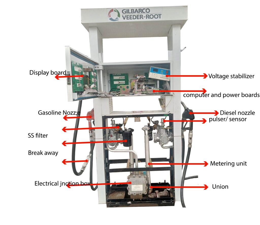
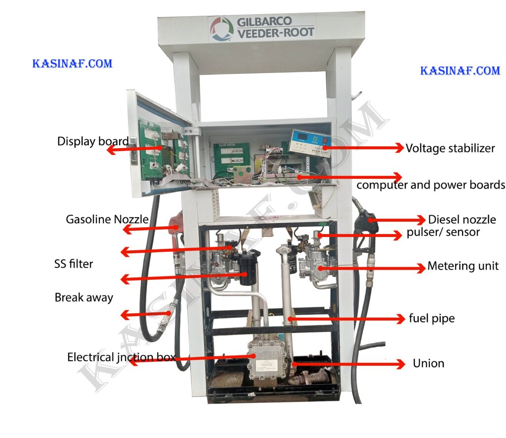
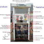
Having explained the parts of a fuel dispenser and its external components above we are going to use those components and functions for explaining the mode of operation of a fuel dispenser.

When the credit card is approved and after inputting the required amount of fuel using the keypad. The customer draws a nozzle from its nozzle rest and puts its spout into the vehicleā€™s tank opening.

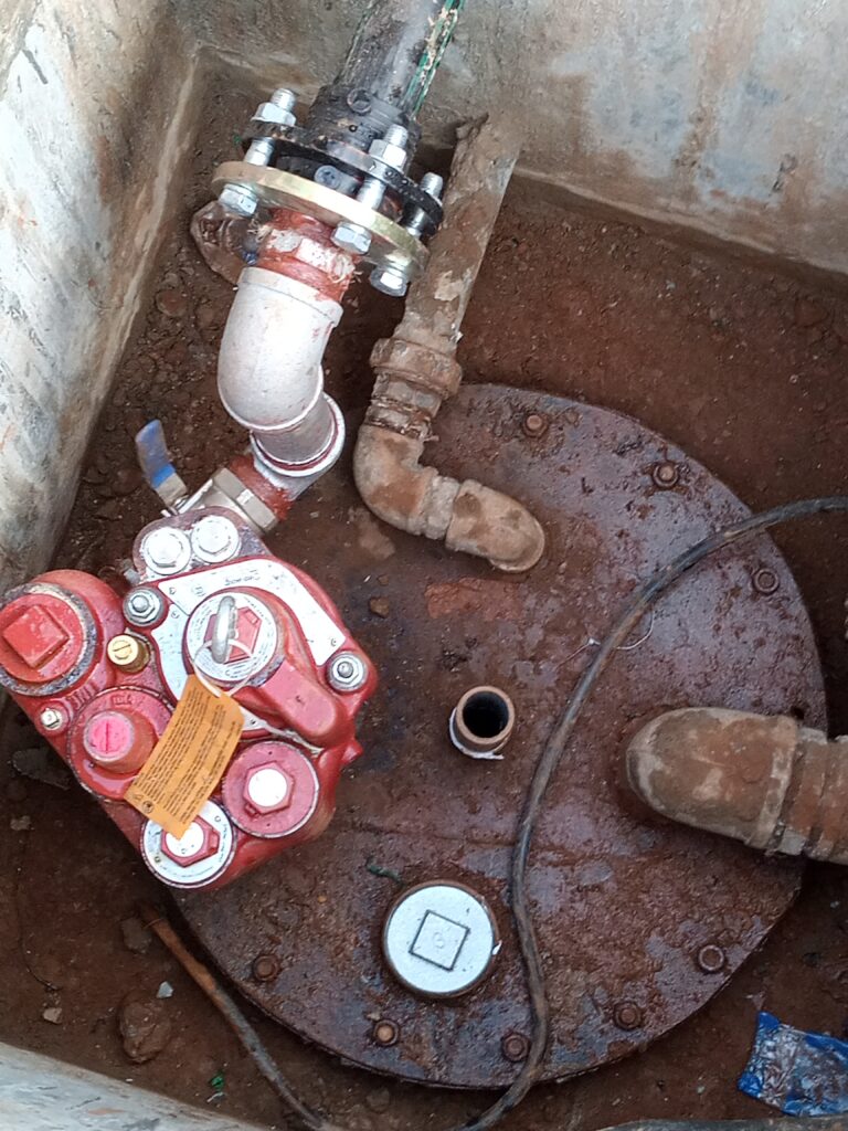
This triggers the fuel dispenser computer to send a fueling command signal, it resets the display to zero, sends a signal to submersible fuel pump control box to power the submersible pump and open the solenoid valve.

See also  Difference between gas pump and fuel dispenser at a gas station explained in detail.

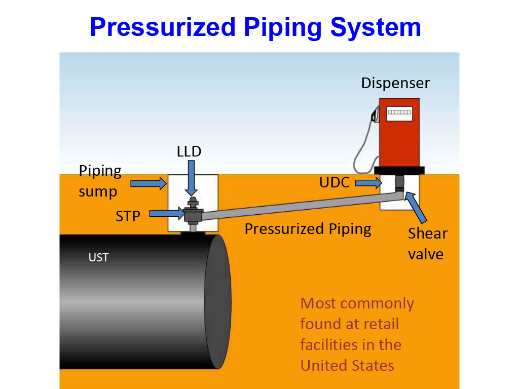
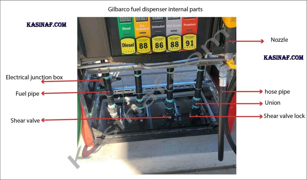
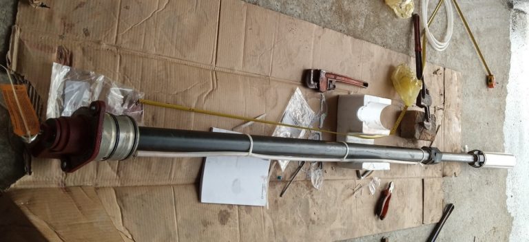
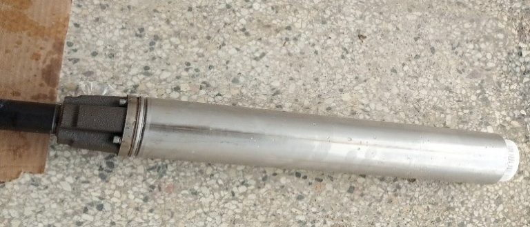
The submersible fuel pump pumps fuel from the fuel storage tank through the product pipeline, this has ball valve for cutting off fuel supply to the dispenser, shear valve to minimize the hazard which may be caused when the gas dispenser is hit by a car. Fuel enters the dispenser through the filter bucket, this removes any foreign material or debris fuel.

The fuel the passes through the feed pipe connecting the filter bucket to the SS filter. The ss filter further filters the fuel before entering the metering unit.

Fuel enters the metering unit through non return valve, this prevents the back flow of fuel after entering the metering unit of the fuel dispenser. Fuel is at a high pressure, when it flows through the metering unit, it pushes the four pistons creating motion, turning the rotating shaft, it flows through the solenoid valve which was opened by the computer unit, through fuel indicator, hose and nozzle into the car.

Rotating shaft of the flow meter drives the cutting notch disc of the pulser sensor to rotate, photo electrical converter converts the metering unitā€™s rotating shaft angular displacement unit into pulser signal. Pulser signal is sent to computer for processing and display.

Placing back the nozzle into nozzle boot or seat, triggers the computer unit to send out shut off signal to the submersible fuel pump and cutting off of power to solenoid valve hence end of fueling.

For preset fueling (fueling where you first input amount), when fueling approaches the preset amount, computer first shuts off the solenoid valveā€™s main valve, fuel dispenser continues dispensing with small amount through the small valve of the solenoid valve. When the preset amount of fuel is reached, computer unit shuts off solenoid valveā€™s sub valve and the submersible fuel pump hence the end of fueling process.

fuel tank with submersible pump installed, this connects to fuel dispenser

simpler process how a fuel dispenser works

Introduction: When a vehicle owner arrives at a petrol station to refuel, the seemingly straightforward process involves more technical complexity than meets the eye. This article aims to delve into the detailed workings of a fuel dispenser, shedding light on the intricate processes that enable the smooth delivery of fuel into a vehicle.

  1. Initiation of Fueling:
  • Customer Authorization: Upon swiping the credit card and obtaining approval, the fuel dispenser prompts the customer to select the type of fuel and specify the desired quantity or value in the local currency.
  • User Input: Using the keypad, the customer inputs the required details, preparing for the fueling process.
  1. Triggering the Fueling Sequence:
  • Nozzle Activation: As the customer withdraws the nozzle from its rest and positions it in the vehicle’s tank opening, a series of events are set in motion.
  • Fuel Dispenser Computer: The fuel dispenser computer sends a fueling command signal, resetting the display to zero and initiating the fueling process.
  • Submersible Fuel Pump Activation: The computer signals the submersible fuel pump control box to activate the submersible pump and open the solenoid valve.
  1. Fuel Flow and Filtration:
  • Fuel Pump Operation: The submersible fuel pump draws fuel from the storage tank through a product pipeline, equipped with safety features like a ball valve and shear valve.
  • Filtration Process: The fuel passes through a filter bucket, eliminating foreign materials, before flowing through a feed pipe to the stainless steel (SS) filter. Further filtration occurs at the SS filter, ensuring clean fuel.
  1. Metering and Pressure Control:
  • Metering Unit Entry: The fuel enters the metering unit, featuring a non-return valve to prevent backflow.
  • High-Pressure Flow: As the fuel flows through the metering unit, it exerts high pressure, driving four pistons that create motion and turn a rotating shaft.
  • Solenoid Valve Control: The solenoid valve, opened by the computer unit, directs the fuel through various components, including a fuel indicator, hose, and nozzle, into the vehicle.
  1. Monitoring and Signal Processing:
  • Flow Meter Operation: The rotating shaft of the flow meter drives a pulser sensor, generating pulser signals.
  • Signal Processing: Photoelectric converters convert the angular displacement of the metering unit’s rotating shaft into pulser signals, which are then sent to the computer for processing and display.
  1. Completion and Shutdown:
  • Nozzle Return: Placing the nozzle back into the nozzle boot triggers the computer unit to send a shutdown signal.
  • Fueling Conclusion: The computer unit shuts off the submersible fuel pump and cuts power to the solenoid valve, marking the end of the fueling process.
  1. Preset Fueling Process:
  • Preset Amount Approach: For preset fueling, when the fueling approaches the preset amount, the computer shuts off the solenoid valve’s main valve, allowing a small amount to dispense through the small valve.
  • Completion of Fueling: Upon reaching the preset fuel amount, the computer unit shuts off the solenoid valve’s sub valve and the submersible fuel pump, concluding the fueling process.
See also  How does a gas station gas pump work?

In essence, the seemingly simple act of fueling a vehicle involves a sophisticated interplay of components and logical functions within the fuel dispenser, ensuring efficiency, accuracy, and a seamless customer experience.

Related topics

1 thought on “How a fuel dispenser works at a gas station | parts of a fuel dispenser”

Leave a Comment

Your email address will not be published. Required fields are marked *