How does a gas station gas pump work?

Spread the love

Gas station suction pump explained in details

Gas suction pump are used at gas stations to pump gas from fuel storage tanks into vehicles

There are many brands for suction pumps used at petrol stations, these include; Gilbarco, Wayne, Tokheim, Tatsuno and may other gasoline suction pumps,

How gas station suction pump works?

What is gas suction pump?

A gas suction pump is a machine that uses an electric motor and a pumping unit connected together by a driving belt to suck fuel from fuel storage tank into the vehicle at a gas station.

Parts of a gas pump and their functions.

Before explaining the gas pump or gas dispenser in details, we have to first know its parts and theirs functions. The parts of Gilbarco, Wayne, Tokheim Tatsuno gas station pumps are similar to all brand, but there are just small differences.

So, we are going to use Gilbarco Veeder Root Frontier (GVR) to explain parts of suction pump for gas. This is a single nozzle gasoline suction pump; it is the best to use in this explanation.

Functions of Each part of a gas pump used at a gas station.

Gilbarco endeavor suction pump parts

1. Ex motor.

This is the driving power of the gas pump dispenser; it is controlled by the computer in the gas dispenser head. It converts electrical energy into mechanical energy which rotates the gas pumping unit.

Ex motor means it is explosion proof motor, it can work in all explosive gasses and can tolerate a maximum surface temperature of 200 or 392

2. Gas pump pumping unit.

This can be a vane pumping unit or gear pumping unit. In the above diagram Gilbarco Veeder Root (GVR) Frontier is using vane pump.

It is driven by Ex motor to suck out fuel from the fuel storage tank, the fuel flows through filter bucket for filtration to the pumping unit, it flows through the pumping unit where air separator separates air from fuel to atmosphere then trough the metering unit with constant pressure and flow amount.

3. Gas station pump metering unit.

It calculates volume of fuel flowing through it and converts this volume into rotating shaft’s angular displacement unit.

This is the measuring unit of gas pump or fuel dispenser. Measures the volume of fuel being dispensed into the car.

4. Ex Pulsar sensor.

Metering unit’s rotating shaft drives the shaft of the pulser sensor simultaneously, the pulser sensor converts the metering unit’s rotating shaft’s angular displacement into electrical signal using photo electricity converter. The electrical signal is sent to the computer in the gas pump head for processing and display.

5. Computer unit.

This is located in the gas pump head. This is a system which has all the gas pump or fuel dispenser required application program software, that has the ability to process and calculate, display, control and communication functions. This is the control center for gas pump and gas dispenser

6. Ex Solenoid valve.

This is used for improving accuracy during preset fueling.

See also  How a fuel dispenser works at a gas station | parts of a fuel dispenser

It has a diaphragm which closes when the preset fuel is over. It has slow flow valve and high flow valve. 

When a gas station fuel pump is dispensing fuel is always in high flow, when its about to reach the set value it goes into slow flow, to achieve accuracy of the set value either in liters or money value $.

7. Ex junction box

Used for connecting the gas pump to power supply.

8. Gas pump nozzle

This is used to deliver fuel into a car. The nozzles used are usually automatic so it guarantees safety when dispensing fuel.

9. Keypad

This is the input device of gas dispenser and gas pump. It is used for preset fueling.

How gas suction pump works at gas station?

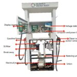
Having known all the parts of a gas station pump above, it is going to be easy to understand how a gas suction pump works. We shall be using the parts explained above and their functions during the explanation.

When a customer reaches a gas pump at a petrol station, he/ she swipes the credit card, when the card is approved. The gas station pump requests him to select the kind of fuel he needs. Then he/ she has to input the amount of fuel either in liters or money, i.e., in dollars.

He removes the nozzle from the gas pump nozzle boot into his car. The pump will immediately start pumping fuel into his/ her car until the preset value in either money or volume is complete. Return back the nozzle into the nozzle boot of gas station gas pump. This is what the customer operating the fuel station pump sees but there is a lot of complex processes and logic functions to be fulfilled in order for the gas suction pump to pump fuel into the car. So am going to explain all these complex processes in this article, without wasting time lets directly dive into it.

When a customer draws the nozzle from a nozzle boot of gasoline suction pump, this triggers the computer unit to send out start fueling command signal. It will reset the display to zero, activate both the ex-motor and solenoid valve, the pumping unit is driven by the rotating Ex motor. These two are connected together by a driving belt.

By using the mechanical power from the ex-motor, the pumping unit sucks fuel from fuel storage tank, they are usually underground fuel storage tanks at most of petrol stations. When fuel is sucked from the tank it first passes through a filter for filtration to remove any foreign material or debris before it enters the pumping unit. When it reaches the pumping unit, it is compressed to increase its pressure. The air separator inside the pumping unit separates air from fuel and disposes it to the atmosphere through the vent pipe and a hole at the side of gas pump. Some gas station pumps have air separates that are outside the pumping unit for example Gilbarco Advantage, Gilbarco Endeavor and many other brands. Gas station pumps use two types of pumping units, these include; Gear pump and Vane pump. These Two types of pumps are explained in details below so stay with me to know everything in detail.

 Pure fuel without air, at a high pressure continues and passes through another filter before it enters metering unit. At the inlet of the metering unit there is a non-return valve that prevents back flow of fuel after entering the metering unit.

When this pressured fuel flows through the metering unit, it pushes the four pistons creating motion. Rotating shaft is turned by this motion, a lot of fuel pass through solenoid valve, hose, fuel indicator and nozzle into the car’s fuel tank.

See also  Procedure for Underground Tank Installation at a Gas Station and fuel station construction.

The rotating shaft of flow meter drives cutting notch disc of the pulser sensor to rotate, photo electricity converter converts the metering unit’s rotating shaft angular displacement unit into electrical signal that is sent to computer for processing and display.

Putting back the nozzle into the nozzle holder and boot triggers the computer unit to send out a command to solid state relay to cut off power supply to the Ex-motor hence stopping the motor leading to stop of fuel dispensing process.

For preset fueling for example when a given volume of fuel or money is fed into the computer using a keypad, when dispensing is approaching the preset amount, computer system will first close the solenoid’s high flow valve, leaving low flow valve open. The gas station pump will continue dispensing with little amount of fuel until the end of dispensing process. This is done to improve on the accuracy when dispensing fuel hence avoiding over delivery.

Mode of operation and construction of Gear pumping unit and Vane pumping unit for gas station pumps.

As stated above, gas station pumps use two types of pumping units, these include the gear pumping unit and vane pumping unit, Gilbarco pump, Wayne pumps Tokheim pumps and other brands use these types of pumps to pump fuel from fuel storage tanks.

The main section of a gas station pump is the hydraulic system. The ex-motor provides mechanical energy to hydraulic system. The ex-motor converts electrical power into mechanical energy which is converted into hydraulic energy by the pumping unit. The fuel pump’s performance directly affects the gas pump or gas station pump’s ability to deliver or dispense fuel. Let’s first look at the vane pumping unit in detail.

Construction and mode of operation of vane pump (pumping unit) for gas station suction pump

Construction and components of a vane pump

Vane pump has filter, overflow valve, discharge valve which are tightly assembled inside the pump body as a whole. Vane pump components are a combination of stator parts assembly and rotor parts assembly.

The stator consists of eccentric sleeve, shaft sleeve and covers on both ends, there are two oval shape window holes at the middle section of the stator assembly, right window is connecting with the inlet hole, return fuel hole of overflow valve, return fuel hole of return valve in the normal pressure chamber, this is called low pressure chamber. Left window leads to fuel separator tube, this is called high pressure chamber.

The rotor is made of rotor shaft and rotor assembly, vane blades can have a forward or back movement within the center of the eccentric sleeve. Circumference of rotor assembly and inner circumference of stator assembly inter cut at point X as shown in the figure X

The height of rotor with vane blade and inner height of stator assembly are equal.

Mode of operation or principle of operation of vane pump used at petrol stations

Having explained all the components of the vane pumping unit, lets start straight away with the principle of its operation.

When the rotor rotates, vane blades will be tightly in contact with inner wall due to centrifugal force. It also has a forward or backward motion with grooves towards the center point of rotor assembly.

The inner chamber of the stator can split into four sectors based on vertical center point as a guideline. It can divide into upper and lower tight sealed zones and left and right transition zones. The angle between the two vane blades on the rotor is 60,thus in the two tight sealed zones there will be one or two vane blades isolating the transition zone. This will cause fuel with in the two inner ends of chamber to be closed and cannot flow through but the fuel with in the transition zone are linked.

See also  Difference between gas pump and fuel dispenser at a gas station explained in detail.

When the rotor rotates in the clockwise direction, (this is observed from the direction showed on the pulley wheel or pump cover). It will have an effect on the suction and compression of fuel fluid with help of the effect of dimensional changes in the two transition zones. This is illustrated in figure x1.

With the center vertical line as the guideline, blade A and B position at the bottom of rotor symmetrically. When the rotor rotates clockwise over a distance of 60, blade B will move from its position to blade A’s position. Fuel between the blades move from center position toward the left chamber. In the right chamber fuel fluid needs to be refilled towards the center position, that’s why its tightly sealed zone become bigger, creating partial vacuum under the effect of atmospheric pressure. The fuel in the storage tank is sucked through pipeline, it enters into pumping unit’s inlet hole, now the left chamber’s sealed zone becomes smaller, fuel fluid being squeezed out through the discharge valve.

When rotor continuously rotates, fuel fluid forms a definite pressure and flow rate. Strength of operating pressure depends on adjustment of overflow valve and its load resistance. Pressurized fuel flows from high pressure chamber into air separator tube, apportion of fuel flow back to low pressure chamber through overflow valve, another portion of fuel flows through discharging valve and flows into the metering unit. When the fuel nozzle is being activated, load resistance will be lower, pressurized fuel overcome the tension of the spring of outlet valve, flows through discharging valve into metering unit.

The overflow valve is under shutoff condition or slightly open. When the nozzle is being shutoff, when the nozzle is being shutoff, fuel pressure increases, the core of overflow valve over come tension of the spring and moves towards the side of the spring under the help of fluid pressure, pressurized oil fluid in high pressure chamber flow to low pressure chamber through the overflow valve, repeating the cycle.  

Exploded view of vane pumping unit of gas station pump showing internal parts

When the adjusting screw is adjusted on the overflow valve, the tension of the spring changes thus adjusting pressure of the hydraulic system and the overflow rates. Turning the screw clockwise, compresses the spring making the pressure needed to push the valve to open to increase. All the fuel or majority of it will flow through the outlet hole. This leads to increase in outlet flow rate. Turning the screw anti clockwise will loosen the spring, making the pressure needed to open the valve to become less. A portion of fuel fluid overflow back to low pressure chamber, hence outlet flow rate is reduced.

2 thoughts on “How does a gas station gas pump work?”

  1. Pingback: How a fuel dispenser works at a gas station - Kasinaf

Leave a Comment

Your email address will not be published. Required fields are marked *